Latest Post
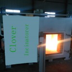
Dual-chamber controlled air incinerator or dual- chamber pyrolytic incinerator
Types of incinerator design acceptable: Dual-chamber controlled air incinerator or dual- chamber pyrolytic incinerator
Materials of construction: The incinerator shall not have any asbestos, asbestos-containing substances, mercury thermometers, and mercury switches. Refractory materials shall be able to meet relevant standards under ISO TC33 and CEN/TC 187.Waste feed system into the combustion chamber batch or continuous loading: For continuous loading, the automatic charging ram or auger feed system shall be capable of injecting small amounts of waste at frequent intervals and should be able to prevent waste from being fed when the combustion chamber temperature is less than 850°C. In addition, the waste feed should only be able opened at or below 50°C in an ambient temperature of 21°C.Primary combustion chamber: Shall be constructed with a casing (reinforced to withstand internal pressures without deflection or damage to the refractory or other components) supported by a structural frame and provided with refractory lining and insulation
Access doors, openings, and gaps: All access doors, openings, and gaps shall be sealed to prevent emission of smoke and exhaust gas and to block admission of air during incinerator operations. Doors exposed to flame or direct heat of combustion gases shall be lined with the same type and thickness of refractory lining and insulation as that used in the combustion chamber
Grate system for the primary chamber Moving grate, traveling grate, reciprocating grate, or rotating drum grate
Primary combustion chamber temperature # 850°C with no cold spots
Secondary combustion chamber: Shall be constructed with an exterior casing (reinforced to withstand internal pressures without deflection or damage to the refractory or other components) and provided with refractory lining and insulation
Secondary combustion chamber temperature 1100°C or higher
Secondary combustion chamber residence time # 2 seconds after the last injection of air in the secondary chamber
a DUCK farm incinerator
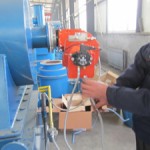
a DUCK farm incinerator, we need to buy a medium size incinerator for biological waste, more specific DUCKS.a pet crematorium in ireland.Equipment Double chamber medical infectious waste incinerator Capacity 10-30 kg per hour Characteristics of waste
Mainly syringes and needles from immunization routine and campaign activities. However, the following average characteristics are considered*:
heating value above 2000 kcal/kg (8370 kJ/kg); content of combustible matter above 60%; content of non combustible solids below 5%; content of non-combustible fines below 20%; moisture content below 30% by weight
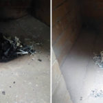
Combustion performance: The medica waste incinerator shall be capable of reducing waste to ash not exceeding 10% of the total combustible charges.
Outdoor installation. The medical waste incinerator will be installed outdoors. All incinerator components shall be suitable for but not limited to outdoor shaded installation, including electric motors, be resistent to corrosion, moisture and related weather elements.
could you please forward me some information. a suitable Incinerator for Incineration of oil, plastic hazardous waste, sludge waste, hazardous filters etc.
installation of waste disposable incinerator system
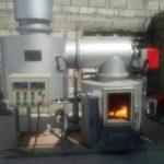
installation of waste disposable system in airport.Incinerator with oil burner
Capacity 2 ton/day, Oil tank 300 l Oil pump 0.4Kw , Burner 0.2Kw
Model : YD Series
Country of Origin : ITALY.- Diesel incinerator.
– 25Kg/h. It will have mainly paper, cardboard and food, though also it will incinerate medical waste. So the incinerator shall be able to handle organic and hazardous waste.
– Spare parts for one year.Burning Capacity: 400kg/ Hr ( Maximum Combustion time is 6 times/ Day)
Chimney External Diameter: not more than 400mm
Fan Power: must not exceed 1.1kw
Voltage: 220V
Oil Consumption: Must not exceed 14kg/hr
Feeding Door Width: not less than 1000x1300mm
Incineration Temparature: 800 Degree or above
Emission:
CO- Must not exceed 100mg/m3
SO2- Must not exceed 400mg/m3
HF( Hydrogen Flouride)- Must not exceed 9mg/m3
NO2- Must Not exceed 500mg/m3
Smoke Dust: Must Not exceed 100mg/m3
– The design should prevent any release of polluting substances into soil, surface water and groundwater.
– Combustion zone has to reach at least 860 degrees under the most adverse conditions with at least 6% oxygen. Since it will treat hazardous and organic waste, temperature has to reach at least 1100 degrees for at least 2 second.
– Flue gases must be cooled to 200 degrees or lower before flue gas treatment. The flue gas cleaning equipment maust be at least two-field electrostatic precipitator/ESP, dust <30mgNm3.
– Thermal efficiency not less than 85%.
– It should be equipped with filter to reduce and contain pollutants from organic and medical waste.
– Easy to operate for almost unskilled workers.
INCINERATOR TESTING AND COMMISSIONING
A flue chimney, 15,000mm long and 560mm diameter shall be constructed from steel sheet, complete with lagging, damper and rain water protection cone. The chimney shall be lined with castable grade diatomaceous concrete mixed with high alumina cement in accordance with BS 4076: 1989.
The damper will control the closing of the door to not less than 85%. The stack is to allow fresh air at the stock’s base so that the flue gases are discharged at not move then 4000 C and that the discharge conforms to the British Clean Air Act, the National Environment Management Agency (NEMA) Act or other relevant acts. .
1.1.4 POWER SUPPLY
The sub-contractor shall supply equipment which are suitable for running on a 415V, 3 phase, 50HZ or 240V, single phase, 50HZ electric power supply.
1.1.5 OIL STORAGE AND SUPPLY
The system shall consist of a bulk oil storage tank, daily tank, transfer hand fuel pump and associated pipe work. Oil from the bulk storage tank will be delivered to a high level daily tank situated in the incinerator room by use of a transfer hand pump and automatic electric pump.
1.1.6 SPARES AND MANUALS
The tenderer is to submit with his tender a list of recommended initial stock of spares together with their prices. A part from the burner spares mentioned here below, the spares prices are not to be included in the main summary of prices schedule but is to be separate and are meant to be ordered later if and when it becomes necessary and convenient to the client. The burner spares whose prices are to be included in the main summary of prices schedule (BQ) are:-
i) 1No. Set of safety controls
ii) 1No. Solenoid valve
iii) 1No. Oil ignition system
iv) 2No. Photo-electric cells
Two sets of operating and maintenance manuals (both for the incinerator and burners) must also be supplied. This include two sets of control schematic diagrams for all the controls and wiring.
1.1.7 BULK OIL STORAGE TANK
The bulk oil storage tank nominal capacity of 10,200 litres and complying with BS 799 part 5: 1975 shall be positioned on three concrete cradles.
The works shall include supply, delivery, assembling, erection, testing, commissioning and setting to work. The tank is to be of welded mild steel type with a design pressure of 40KN/m2 and storage temperature of 240 C. It is to be located adjacent to the incinerator and boiler house.
The tank shall be cylindrical with dished end and be constructed of 6mm thick block mild steel plates in accordance with BS 1966. Number one quality galvanised materials shall not be used.Welded construction parts shall be sprayed.
E-4
The tank shall be pressure tested with a total head of water or equivalent, measured from the base of the tank, and equal to 1½ times the sum of:
(i) The height of the tank and
(ii) The design head above the top of the tank that is 3.5m of water.
The pressure shall be raised slowly and steadily until the specified test pressure is reached and that pressure shall be maintained for a period long enough to permit a thorough examination to be made to ensure that the tank is sound enough and shows no leaks or undue distortion. Welded joints shall be radiographed and a certificate issued. Should any defects be found, they shall be made good and the test procedure repeated until the tank is certified to be sound. The tests shall be carried out in the presence of the Engineer and subsequently, the sub-contractor will provide the Engineer with the test certificate.
The tank shall then be cleaned externally and provided with rust inhibiting primer before applying 2No. coats of bituminous paint. The inside shall also be cleaned and purged of any foreign matter before setting to work.
Ladders and platforms shall be thoroughly cleaned and freed from rust and scale and painted with a priming coat of approved paint.
The tank shall be provided with the following:-
(i) 450mm bolted inspection covers with liquid and vapour tight joint made with a gasket of fuel resistant materials.
(ii) 75mm (3”) vent socket screwed B-SP and pipe at the higher end of the tank with an unloading device to prevent the rise in tank pressure above the design pressure. The vent pipe shall be free from bends and shall have a continuous rise while being as short as convenient. It shall terminate in open air in a position where it cannot be tampered with. The open end shall be turned down and fitted with an open mesh wire cage.
(iii) 65mm diameter filling pipe with hose coupling connection
(iv) 50mm diameter gauging connection with lockable cap.
(v) 50mm diameter supply pipe
(vi) 25mm diameter water drain-off value
The tenderer shall supply hydrostatic oil contents gauge (level indicator) or a
properly calibrated stick (of dip tape) and access ladder to the top of the tank.
The filling pipe shall be extended inside the tank to within 150mm of tank bottom,
complete with anti-siphoning device.
The following information shall be permanently and clearly marked on the tank on the
centre line near the outlet connection.
• Gross capacity in litres
• Test pressure
• Date of test
• Maximum allowable working pressure
• Manufacturer’s name of trade mark
• Year of manufacture
• The number of British standard and type of tank
The tank shall be installed with a 25mm fall towards the water drain-off tapping point. The supply socket shall be extended inside the tank to prevent ingress of water in the supply line. The main contractor shall construct tank supports and bund walls to detail drawings produced by the sub-contractor. A valued drain off from the lowest part of the tank shall be provided complete with tail pipe and a provision for hose connection.
E-5
1.1.8 TRANSFER HAND PUMP
A semi rotary hand pump shall be provided for filling the day storage tank from the oil drum. It shall be installed complete with all the necessary plumbing fittings and accessories.
1.1.9 DAILY SERVICE TANK
A daily storage tank of nominal capacity 1,800Litres shall be mounted at 2.5 metre high level in the incinerator room. Tank shall be manufactured from 6mm thick pressed steel plates of 1220mm x 1220mm black mild steel sheet, complete with bolted cover and adequate venting. The tank shall conform to BS 799 part 5 1995 and be provided with a contents sight tube. The tank shall be lagged with 50mm thick fibre glass insulation of 0.4W/m2 thermal conductivity and finished with 20SWG galvanized sheets cladding.
The tank shall be tested for any leaks of which if any is detected will be made good before the tank is painted externally with rust inhibiting paint. Tank to be securely bolted.
1.1.10 AUXILLIARY EQUIPMENT
All pipework used in the oil storage systems shall be to B.S. 1387 heavy grade. Joints shall be screwed, and sufficient unions must be provided to allow easy dismantling the equipment.
A 25mm diameter fire valve of the quick action lever operated dead weight type shall be installed, in the oil flow line. This shall be held in the open position by a light gauge steel cable attached to a fusible link. The fusible link shall be mounted directly over the burner. The warm burner oil feed pipe from the high level day tank shall be heated by an electric tracing tape properly wrapped around the pipe. The pipe shall then be insulated with 25mm thick fibre glass insulation and finished with gauge 22swg galvanized steel sheet.
The supply pipe from the bulk oil storage tank to the high level day has been installed by others but the tenderer shall allow for connection to the high level day tank. The tenderer shall also supply and install high capacity strainers along the supply pipe and the burner feed pipe.
1.1.11 PIPE SUPPORTS
The variety and type of supports shall be kept to a minimum and their design shall be such as to facilitate guide and secure fixing to match concrete masonry or wood.
Consideration shall be given when designing supports to the maintenance of desired pipe fall and the restraining of pipe movements to a longitudinal axial direction only.
The sub-contractor shall supply and install all steel work forming part of pipe support assemblies and shall be responsible for making good any damage to builders work associated with builders work installation.
Pipe runs shall be secured by clips connected to pipe hangers, wall brackets or trapeze type supports. ‘U’ bolts shall not be used for clips without prior approval of the Engineer.
The sub-contractor shall submit his entire proposal for the pipe supports to the Engineer for approval before any erection work commences.
1.1.12 ELECTRICAL WORKS
All wiring between items, plant and controls shall be executed by the tenderer. The tenderer shall provide adequate supervision to ensure that electrical connections are correctly made to all items of equipment and controls supplied by him, all to the Project Manager’s / Engineer’s satisfaction.
E-6
1.1.13 INCINERATOR TESTING AND COMMISSIONING
The tenderer shall test and commission the incinerator in the presence of the Engineer.The tenderer shall also provide sufficient oil to last at least two (2) hours. The tenderer shall test and commission the incinerator in the presence of the Engineer and verify that the incinerator is functioning according to the specifications laid here-in and in the catalogues and manuals from the suppliers of he incinerator.The incinerator performance test shall be carried out in accordance to BS3316: part 4:1987.Should any defect be detected, it shall be rectified and the testing process repeated to the Project Manager’s satisfaction.
1.1.14 FIRE INSTRUCTION NOTICE
Proceed and procure and install as below;
Print fire instruction on the Perspex plate, 3mm thick with White Colour
Background measuring 510mm lengthx380mm width as follows;
castable high quality refractory lining and incinerator shell
The incinerator shall have chimney, castable high quality refractory lining and incinerator shell, perforated blind for the primary and secondary combustion chambers and air circulation system.
The incinerator shall also have the following:-
• Ash door
• Primary and secondary burners and fans
• Temperature indicator devices
• Electrical wiring from the local isolator
• FD fan
• Air receiver
• Air ductwork complete with air dampers
• Pressure and temperature gauges
• Fully wired control panel
The bulk oil storage tank shall have a capacity of 10,200 litres and be placed at 0.5m above ground on a firm concrete cradle, complete with the following:-
• Drain pipe
• Vent pipe
• Oil level indicator
• Access ladder to the top of the tank
• Coating of the tank with at least 2No. coats of bituminous paint
• Manhole cover complete with a gasket
• Dip stick
• Any other necessary accessory.
E-2
The daily oil tank of capacity 1,800 litres and size 1220x1220x1220mm pressed steel tank high shall be placed 2.5 metres high above finished floor level on a steel stand, firmly secured on the ground and the steel members to be bolted. The daily oil tank shall have an oil level indicator, access manhole, washout, overflow, inlet and outlets connections and gate valves.
The interconnecting pipe of 50mm diameter between the two tanks shall be class ‘C’ black mild steel pipe, complete with a 50mm diameter strainer. The burner fuel supply pipe from the daily tank shall be a 25mm diameter class ‘C’ black mild steel.
The following shall also be supplied
• 25mm diameter fire valve
• 25mm diameter high capacity strainer
• heating tap along the burner supply pipe, 25mm diameter
The burner supply pipe shall have 25mm thick fibre glass insulation and finished with gauge 20SWG galvanised steel sheet.
The tenderer shall provide all the necessary controls for proper safety and satisfactory working of the installation.
1.1.1 BURNER
The burner shall be suitable for 35 sec redwood No. 1 scale fuel oil. It shall be robust in construction and be manufactured in cast iron or other suitable materials complete with mounting plates. It must be easily mountable and demountable for ease of cleaning and maintenance. The burner shall have an adequate supply of oil which will readily ignite and burn in a safe manner. Adequate provision shall be provided to prevent any solid matter in the oil, or any matter that may separate out from the oil from damaging any components or chocking of any orifices or valves. The free filtering area should be sufficient to ensure that the filter does not need dismantling for cleaning more often than once a year. The burner shall have flame supervision by photo-electric cell with synchronous sequence controller for automatic start up, running and shut-down of the burner.
The burner shall have all the necessary controls e.g.Solenoid valves, ignition controls, photo electric cell fuel safety controls, low pressure fuel supply cut-off etc.
The burner shall conform to BS 799: part 3 and 6 1981 or any other relevant British standard.The burner shall be as NU-WAY models or equal and approved.
1.1.2 CONTROLS
The incinerator shall operate in an automatic manner with all the necessary controls. These controls are to include safety elements such as flame failure unit, pilot lamps, fuses, starters, overload contactors, ON and OFF switches for burners and fans, combustion chamber temperature indicators for primary and secondary chambers etc.
i) Electric ignition switch ‘ON’ before the oil is supplied
ii) Delayed return to re-start position to allow purging
iii) Re-start after temporary electric supply failure
iv) Positive safety lock-out in case of flame failure from whatever cause.
v) Red signal light on control panel to indicate safety lock out
vi) Photo electric protective cell as flame failure device.
The controls shall be mounted on suitable control panel to be installed in a position easy to read and control from the charging door side of the incinerator.
The control panel shall be fabricated from anodized, 16SWG, mild steel sheet.